Spanky Posted December 4, 2019 Report Share Posted December 4, 2019 2 minutes ago, K Cooper said: Can you imagine the price in three years? Time to take options! It will take two Houston Hats for you to get one board of it! Quote Link to comment Share on other sites More sharing options...
Coop Posted December 4, 2019 Report Share Posted December 4, 2019 Cummin your way. Quote Link to comment Share on other sites More sharing options...
wtnhighlander Posted December 4, 2019 Report Share Posted December 4, 2019 @Bmac, all three of those chairs are incredibly beautiful! At the risk of offending anyone, can I ask if you know of a design the takes a smaller footprint? The Maloof style is pure grace, but just eats so much space.... 1 Quote Link to comment Share on other sites More sharing options...
Chestnut Posted December 4, 2019 Report Share Posted December 4, 2019 I'm amazed at how fast you can churn these out. The end result is beautiful and does not look like you spent less than 100 hours on it. 1 Quote Link to comment Share on other sites More sharing options...
Mark J Posted December 4, 2019 Report Share Posted December 4, 2019 Whoa! Between the grain, finish and contours, that takes your breath away. I can't imagine ever tackling a project like that. 1 Quote Link to comment Share on other sites More sharing options...
Bmac Posted December 4, 2019 Author Report Share Posted December 4, 2019 10 hours ago, wtnhighlander said: @Bmac, all three of those chairs are incredibly beautiful! At the risk of offending anyone, can I ask if you know of a design the takes a smaller footprint? The Maloof style is pure grace, but just eats so much space.... True, the footprint is big. What dimensions were you thinking of reducing? I'm sure you could make the rockers 5-6" shorter with no problem, you could change the angle of the back legs to 3 degrees instead of 6 to decrease width at the top, and you could probably even lower the back rest some. I think all those are probably simple enough mods. I think the look would not suffer too much and it would likely be just as comfortable. 1 hour ago, Chestnut said: I'm amazed at how fast you can churn these out. The end result is beautiful and does not look like you spent less than 100 hours on it. You know, I honestly was a little shocked at my time. I was wondering if I was shaving time off like rounding down 15 minute here or there, but still if I did that I would have only added an hr or two in the end. I think my speed is based on a few things, first it was my 5th rocker and I'm not sure how many sculptured pieces before this. Second, I've made enough of this Maloof furniture that I don't have to think twice about my shaping. My mind already envisions it and my hands have had practice getting there. In the beginning it's typical to be hesitant and go much more slowly in fear of making a mistake. I've over come that fear and just plow ahead. Finally, and probably most significant, I have developed a system. Combining the tools I'm comfortable with and a process I refer to as power shaping/sanding I am able to work faster. Combining the RAS, the interface pads, and the rasps I do 90% of the rough shaping with those. I love the Festool 90 Rotex for it's small shape/profile, light weight, and ability to use with one hand and not get fatigued. The 90 may not be the most powerful Rotex, but it helps immensely with the process. I think any brand of smaller sander would work with the interface pad, but I do the the aggressive mode that Rotex offers. 1 hour ago, Mark J said: Whoa! Between the grain, finish and contours, that takes your breath away. I can't imagine ever tackling a project like that. I'm sure you can tackle this project, those crazy shapes you make take my breath away. This project is just like any other, one step at a time. 2 Quote Link to comment Share on other sites More sharing options...
Spanky Posted December 4, 2019 Report Share Posted December 4, 2019 Bmac I think the next rocker needs to be curly white oak. But you will need to be big buddies with a sawmill guy that cuts alot of white oak to get 10/4. Quote Link to comment Share on other sites More sharing options...
Bmac Posted December 5, 2019 Author Report Share Posted December 5, 2019 34 minutes ago, Spanky said: Bmac I think the next rocker needs to be curly white oak. But you will need to be big buddies with a sawmill guy that cuts alot of white oak to get 10/4. I know, none of this 4/4 stuff is going to get that done. I do have quarter sawn 9/4 drying on my property, but that stuff dries slow!!! Quote Link to comment Share on other sites More sharing options...
Coop Posted December 9, 2019 Report Share Posted December 9, 2019 I’m still on a high from this! Put a Christmas bow on it and I’ll be able to sleep! 1 Quote Link to comment Share on other sites More sharing options...
legenddc Posted January 9, 2020 Report Share Posted January 9, 2020 I finally caught up on this. Amazing work and it's clear that you've developed a process that works for you. The pictures of all 3 together are great! 1 Quote Link to comment Share on other sites More sharing options...
jgt1942 Posted July 9, 2020 Report Share Posted July 9, 2020 I just found this post and LOVE it! What a beautiful piece of work. BMAC, MUCH thanks for the EXCELLENT post! I'm getting ready to build my first two chairs for two granddaughters. Because I've never built one I was going to first build one from scrap 2x4s and hopefully make all of my mistakes there. I've been watching a video by Scott Morrison and IMHO your post is as good or better. Because the girls are small I've decided to reduce the plans to 75% of the original size. I did this in CorelDraw with a plug-in. I've printed the new plans, taped all the sheets together, pasted them on 1/4" BB plywood, cut them out. I've preped the wood. I'm at the point where I'm ready to mark with the templates. 2 Quote Link to comment Share on other sites More sharing options...
wtnhighlander Posted July 10, 2020 Report Share Posted July 10, 2020 @jgt1942, please post pics! We love see one another's work in progress. A project journal for those chairs would be wonderful. 1 Quote Link to comment Share on other sites More sharing options...
Bmac Posted July 10, 2020 Author Report Share Posted July 10, 2020 4 hours ago, jgt1942 said: I just found this post and LOVE it! What a beautiful piece of work. BMAC, MUCH thanks for the EXCELLENT post! I'm getting ready to build my first two chairs for two granddaughters. Because I've never built one I was going to first build one from scrap 2x4s and hopefully make all of my mistakes there. I've been watching a video by Scott Morrison and IMHO your post is as good or better. Because the girls are small I've decided to reduce the plans to 75% of the original size. I did this in CorelDraw with a plug-in. I've printed the new plans, taped all the sheets together, pasted them on 1/4" BB plywood, cut them out. I've preped the wood. I'm at the point where I'm ready to mark with the templates. Thanks for the kind words. Doing these rockers are a real pleasure, hope you experience that in your build. Would love to see pics of your project too. Project journals are my favorite part of this forum and I've become a better woodworker by posting my work! 1 Quote Link to comment Share on other sites More sharing options...
Coop Posted July 10, 2020 Report Share Posted July 10, 2020 @jgt1942, I too will certainly follow you build. However, and not to take away from Bmac’s rockers as they are way beyond my expertise, @treeslayer built his grandchildren small folding chairs and I bet he will be willing to share with you. And the only reason I say this is that these younguns grow so fast, they may be too big to use them in a year or two. If it were me building them, they would outgrow them before I was halfway finished! Either way, looking forward to your build. Quote Link to comment Share on other sites More sharing options...
jgt1942 Posted July 10, 2020 Report Share Posted July 10, 2020 OK here goes... This will be a combination of post because I'm working on several different things that weave together. I will first build a chair out of scrap 2x4. As I said, I hope to make all of my mistakes with it. I'm still working on the G700 setup and I have finished what I will call phase one. Because the shop is in such a state of flux I decided to run a 20' flex pipe. This was purchased from Rocker several years ago and I had never used it. I connected the two sections with a coupler, attached one end to the G700 and the other end has been connected to my DeWalt DW746X tablesaw and my Hammer A3-31 planer/jointer (NOTE I'm only connecting to one machine at any time for now, thus I'm moving the hose from one machine to the other). First I had enclosed the tablesaw, the image of the tablesaw does not show all of the sealing I did. Partly because I'm anal at times (this was one of those times) most likely I went overboard. This took me a few days partly because of health, some days I can work several hours and other days I only last a few minutes. I've completed the sealing except for the tilt opens, yesterday I received some magnetic sheets I had ordered. Hopefully today I will finish. Currently, I do NOT have any collection above the blade and it is needed. When I connect the G700 to the saw it does a super job of collecting MOST of the dust. The only thing I see is what comes from the blade. I'm not sure just when I will tackle this, I have to think about the solution I want to implement and thinking is hard. The A3-31 presented another issue in that the port was not a standard US size and the only solution seemed to be placing an order with Felder (Hammer) for a fitting. This was going to be VERY expensive so I decided to make a custom fitting. I remeasured the port on the A3-31 (4.765"). I went to Lowes and purchased various a section of PVC in different sizes. I purchased several different sizes because I was going to make custom fittings for several different tools. Ops, I don't know how to get the images inline with the text. I need to glue-up some 2x6's to make a jig. In the image of the jigs, the one on the left was for a custom fitting on my bandsaw, the one on the right was for the A3-31. These were turned on my wood lathe. I tuned a recess in the top of the jig (see the image of both jigs) so I could insert the jaws of my chuck. I was then able to turn the other end to reduce the fitting. NOTE: It may be possible to expand the pipe without a jig "if" is a small amount. I tried but failed, possibly because I did not get the pipe hot enough, later I will experiment more with this. Using a heat gun (I had a dual setting heat gun that I purchased from Ace Hardware several years ago), wearing gloves (a this is going to get HOT), continuously rotate the pipe and apply heat. At some point you will see the PVC starting to constrict, test the flexibility and when it easily flexes turn off the heat gun, push the fitting onto the jig (NOTE I discovered that it is best to securely clamp the jig in a vice) and let it cool. Now it was time for a test fit, looks GOOD! After the pipe cooled (if you remove the fitting before it cools the shape will change as it further cools), I repeated the preceding for the end I needed to reduce. Again let it cool. Now it was time to connect everything. At this time I was happy but did notice that the fitting I made was a bit loose when I put it on the A3-31 port. I disconnected the fitting, reheated the expanded end (this is the end that goes on the A3-31), when it started to constrict and was flexible I pushed it on the A3-31 fitting and let it cool. Now I had a very tight fit, perfect! 1 Quote Link to comment Share on other sites More sharing options...
jgt1942 Posted July 10, 2020 Report Share Posted July 10, 2020 There are a lot of homes being built in my area and most contractors will allow you to pick up wood from their scrap piles. Most often this is 2x4's with lots of nails in them. I carefully remove the nails, I also used a Small Handheld Metal Detector (similar to https://www.amazon.com/BRELLAA-Handheld-Adjustable-Sensitivity-Vibration/dp/B07PV363BJ/ref=sr_1_17_sspa?dchild=1&keywords=metal+wand+dec&qid=1594399463&sr=8-17-spons&psc=1&spLa=ZW5jcnlwdGVkUXVhbGlmaWVyPUEzQ05FWklWM1A1QldGJmVuY3J5cHRlZElkPUEwNzczODI3MzM2NzNXR1dKSDQyQyZlbmNyeXB0ZWRBZElkPUEwMDUyNzg3MUVOTUNFNkUxTDVJRiZ3aWRnZXROYW1lPXNwX210ZiZhY3Rpb249Y2xpY2tSZWRpcmVjdCZkb05vdExvZ0NsaWNrPXRydWU= the current price is MUCH lower than I paid several years ago) to ensure there was no hidden nails. I then planed the two wide sides and trimmed off the two smaller sides on the tablesaw. Yes I realize that some of the boards are warped and I should have done a better job but it will all work out. I cut what I knew would be more than enough wood. The pieces are about 70" long The next image shows how much dust the tablesaw generated on top of the saw. This should be eliminated when I implement a blade collection. Compared to what I had before enclosing the TS this is almost nothing. I then cut all the boards I needed for the chair. Each piece is a bit longer at this time. I'm using a cut list that I have modified to show the sizes of each piece at 100% and 75%. With a felt pen I marked the ends of all boards, also note that I have marked for the 3 degree cut. Obviously my marking is not the correct angle, I just need to ensure I cut the board on the correct side at the correct angle. Initial glue-up to match the cut list, at this time the width is NOT correct, this will come later. Using my digital angle tool I set the TS blade to 3 degrees. Double check the angle on the seat boards. Here is where I noticed that the boards were NOT wide enough, just a bit off, OH DARN. I cut three boards to length and then ripped 5 one inch pieces and glued them to each seat board. I'm now ready to cut the seat boards with the 3 degree angle. FYI - so how is the G700 doing after all that planing and cutting? First I noticed that the intake port on the G700 was almost 100% blocked. When I cut the narrow edge off of the 2x4 sometimes a VERY thin strip was cut. Sometimes the thin strip broke into short pieces and were sucked down past the blade and were stopped by the safety grid on the G700 intake port. I can remove the grid but this introduces a safety hazard. With the grid removed it would be possible for someone to extend their hand into the port and into the impeller. I've never done this and imagine it would hurt a bunch. Because the G700 is new to me and I'm still trying to decide if it is the correct unit for me, I will NOT remove the grid at this time. When I was making the last cuts I noticed that the pitch of the G700 had changed, this was due to the blockage. When I looked at the front of the G700 (it was still running) I noticed that the bin full light would sometimes come on. If the bin is full the G700 will automatically turn off. I opened the bin and noticed that both bins were almost full. Here is a close-up of the large bin and small bin I was surprised to see the large chips in the small bin. Per the write-up, the large dust should be collected in the large bin and only the fine stuff should be in the small bin (this is my understanding). Now that the glue has dried on the seat pieces I can now cut the 3 degree angle. Later... 1 Quote Link to comment Share on other sites More sharing options...
wtnhighlander Posted July 10, 2020 Report Share Posted July 10, 2020 Dust collection seems greatly improved. I like your custom port connector solution. Quote Link to comment Share on other sites More sharing options...
jgt1942 Posted July 10, 2020 Report Share Posted July 10, 2020 1 hour ago, wtnhighlander said: Dust collection seems greatly improved. I like your custom port connector solution. Thanks, you are 110% correct, HUGE improvement. BTW how do I get my pictures to be inline with the text as BMAC did? Any idea as to why PNG images are not allowed? How do you get the "Drag files here to attach" to work? When I try I get the circle with the line through it. Quote Link to comment Share on other sites More sharing options...
wtnhighlander Posted July 10, 2020 Report Share Posted July 10, 2020 Sorry, I mostly use the mobile web version of the forum pages. In this mode, use the 'click to choose files' link to upload, the place the cursor where you want the image to appear within the text, then tap tge '+' symbol in the corner of the image. As for why png isn't accepted, it may be a setting that can be changed by the admin. @Kev, any thoughts on that? Quote Link to comment Share on other sites More sharing options...
jgt1942 Posted July 12, 2020 Report Share Posted July 12, 2020 mac I have a few questions, this is my test build with scrap wood. (1) what size dominio did you use? (2) I'm confused about the dominio cut for the seat. I've made my 3 degree cuts and a reference line on the front end of the seat for the dominio at 1/2" from the bottom of the board. I understand how to make the cuts on boards 1, 3 & 5, (e.g. just put the bottom of the board and D500 flat on the workbench line-up the D500 with the mark on the top of the seat and cut. I sorta get lost when it comes to boards 2 & 4. In the above image After making the 3 degree cuts I clamped the boards together. I made the dominio reference marks The pink dots represent that the reference line is 90 degrees to the outside edges of the seat. When I make the cut in boards 1, 3 and 5 the D500 is resting on the workbench and the board is flat on the workbench. My D500 has the guide UP, it is set for the tightest cut. On the left side of S2 the dominio reference line actually goes up whereas on the right side the reference line goes down. Now I set the D500 guide to 87 degrees, flip S2 upside down, place the guide on the board and make the cut. I inserted the dominio in the slot and pushed the other board on the dominio, following is my results. Note the large gap I made another test cut with the guide set at 84 degrees, following is my results. Note that the gap is much smaller. My thinking is: Both boards have a 3 degree cut, when they are pushed together the net effect is I have a 6 degree cut. The dominio is parallel to the bottom of S1 and it should go into S2 at a 6 degree angle. Now I'm thinking, because the reference line on the right side of S2 goes down rather than up I'm in trouble with the D500 and cannot use the same setting as I did for the left side. Possible solution Make the cut on the left side of S2 and left side of S4 the same way I made the cuts on S1 & S5. If I'm thinking correctly the cuts on the left side of S3 and the right side of S3 would then be made by placing the D500 on the bottom and the guide at 84 degrees. Am I out in left field all by myself and totally lost. It's late and I'm too tired to try this tonight, hopefully tomorrow. Quote Link to comment Share on other sites More sharing options...
jgt1942 Posted July 12, 2020 Report Share Posted July 12, 2020 On 7/10/2020 at 5:22 PM, wtnhighlander said: Sorry, I mostly use the mobile web version of the forum pages. In this mode, use the 'click to choose files' link to upload, the place the cursor where you want the image to appear within the text, then tap tge '+' symbol in the corner of the image. As for why png isn't accepted, it may be a setting that can be changed by the admin. @Kev, any thoughts on that? OK I got the pics inline with the text. Originally the drag-n-drop was not working for me. After reading your answer I positioned the cursor in the location where I wanted the image, dragged-n-dropped the image in this area and the image appeared where I wanted it. If I accidentally dropped it in the wrong area in the bottom section of the window where it shows the images I've uploaded I mouse over the trashcan and click it. The image is entirely removed from the post and I can try again. 1 Quote Link to comment Share on other sites More sharing options...
Bmac Posted July 12, 2020 Author Report Share Posted July 12, 2020 OK, this is a tricky part and I use two methods. First if you put your boards down with the tops up and try to domino with the boards on the bench, you will have a problem when you have an acute angle since the domino doesn't adj to an acute angle. So, do the joints you can with the boards and the domino resting on the bench. Now, the joints where you can't do this; flip the boards over and domino from the side of the board now facing up. Make sure you adj the height of the domino and keep the domino in the bottom 1/4 of the board and do both boards involved with the joint this way. To help you can adjust your domino fence to match the angle like I did. Quote Link to comment Share on other sites More sharing options...
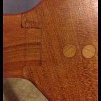
jgt1942 Posted July 12, 2020 Report Share Posted July 12, 2020 Thanks Bmac! I did it slightly different and think I have it. Now to see if I can explain. I'm using the 5x30 Dominio I plan to install dominios along the front and the back area only. The D500 cutting width will be set for 13mm, the narrowest setting, for the rear cut and 19 mm the middle setting, for the front. Some of the cuts will be made from the top side of the boards and others will be made from the bottom side of the board. Reference the preceding image: The "orange" cuts labeled "B" were made with the D500 resting on the bottom of the board, the board was positioned on the tablesaw top with the topside down. The "green" cuts labeled "T" were made with the D500 resting on the top of the board, the board was positioned on the tabletop with the topside up. For this cut is is necessary to adjust the D500 depth. The preceding image is a "Bottom" cut On the bottom of the boards 1&2 and 4& 5 a reference line was drawn across boards for the middle of the dominio cut The guide angle on the D500 was set to 87 degrees The D500 depth is zero, this will position the cut about 1/2" from the bottom The guide is firmly press down on the board The D500 cutting area is firmly pressed against the 3 degree tablesaw cut Repeat this for boards where 1 & 2 will join and 4 & 5 will join. Note if you are installing multiple dominios only cut one slot in . each board at the narrowest setting. The other slots should be cut with the middle setting. The preceding image is a "Top" cut On the top of boards 2&3 and 3&4 a reference line was drawn for the middle of the dominio cut The guide angle on the D500 was set to 87 degrees The D500 depth is NOT zero. Firmly press the guide down on the top of the board, firmly press the D500 cutting area firmly against the 3 degree side of the board, loosen the fence height locking lever, lower the body of the D500 until the base is touching the tabletop, lock the fence height locking lever, this will position the cut about 1/2" from the bottom. In the preceding image note that the Guide and the cutting area are making full contact with the board. The base is only touching the tabletop where it meets the board. Repeat this for boards where 2&3 will join and 3&4 will join. Note if you are installing multiple dominios only cut one slot in each board at the narrowest setting. The other slots should be cut with the middle setting. Now insert the dominos and you should have something like the following. Note that there are no spaces between the boards. Obviously I'm scrap from my scrap. Quote Link to comment Share on other sites More sharing options...
Bmac Posted July 12, 2020 Author Report Share Posted July 12, 2020 No, you did it the way I was trying to eplain, some cuts from the top and some from the bottom is the key! Quote Link to comment Share on other sites More sharing options...
jgt1942 Posted July 12, 2020 Report Share Posted July 12, 2020 Bmack, thanks again. It just seems that I did it differently. My head was spinning! I first marked the seat (remember I'm working with scrap 2x4s for this build) for the location of the cuts and if they were Top or Bottom. I decided to put the narrow cut at the back where the spindles will go and the loose cut at the front of the seat. I made all the cuts. As Bmas stated this is a bit confusing and if you don't do a good job of marking everything and paying very close attention you will make mistakes and cut in the wrong place (I did cut incorrectly on the side of one board but it should not be a problem). After I made the cuts I started the glue-up by first putting glue in the cut and glue on the side of that board. The board that goes against this got only a bit of glue in the cut, there is no real reason to put glue on this face. I repeated these steps until the seat was assembled and then applied clamps. I did notice that I did not take enough care to align front-to-back but you can easily see there are no gaps between the joints. Here is a different angle. I'll let it set over night before I do anything else. Tomorrow I will re-read Bmac's next steps. Later I will post Bmac's instructions and the notes that I have added as a PDF file. Originally I intended to scale down the plan from 100% to 75%. Today I discovered that the file I kept was scaled down to 71% and for some reason I did not keep the 75% scale. Oh well, this will be close enough for the girls. If I have enough summers left I will make them a 100% scale in a few years. Quote Link to comment Share on other sites More sharing options...


Recommended Posts
Join the conversation
You can post now and register later. If you have an account, sign in now to post with your account.